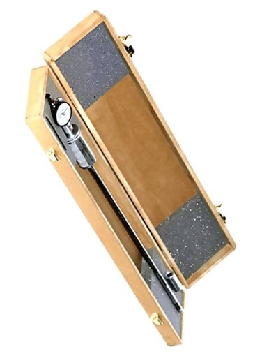

Western Instruments N88-TS-I Tube Sheet Pit Gauge, Inch Indicator

This manual assumes the operator has read Western Instruments documentation covering Dial Indicator Pit Gauges and has used these, or similar instruments extensively. In short this is not the first Pit Gauge or precision metrology device the operator has used.
The Tube Sheet Pit Gauge is designed to fit inside most inch OD (0.500i or 12.7mm) Boiler Tube, where the resulting Inside Diameter is just over 0.375 inch or 9.5mm. Without having stating the obvious, the Tube Sheet Pit Gauge will also test larger tube where reaching into the Tube is necessary.
| The overall length of the Tube Sheet Pit Gauge is 23 inch (600mm), with a working length of 12 inch (320mm) on the minimum diameter. The overall length is approximately 20 inch (500mm) with an overall diameter (clearance) of 1 inch (38mm). Specials can be ordered to reach into tubes much farther, within practical limits, and have been manufactured with a working lengths up to 1.5 meters. | 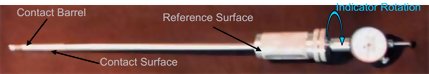 |
With the standard design of the Tube Sheet Pit Gauge, the operator doesn't typically have to be concerned with any deflection of the Shaft while in use. However, the deflection of specials that have been order longer, can be a concern, especially at the maximum length. When a very long Tube Sheet Pit Gauge is in use, the operator must be completely mindful of keeping the Contact Surface flat against the work-piece. Due to the flexibility of the long shaft, the operator will need to be inventive to block or hold the Contact Surface up against the target area.
Dial Indicator
The Axially Mounted Dial Indicator is able to rotate through 360, thus the Barrel of the Pit Gauge can rotated to any radial position, within the tube ID, to measure Pits, allowing the operator to have a clear view the Dial face.
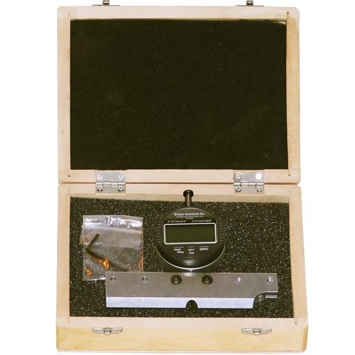
| Any of Western Instruments 3 Models of Dial Indicators (Imperial, Metric, or Digital) can be used on the Tube Sheet Pit Gauge. No special work is required when changing Dial Indicators, just the switching out of the standard parts covered in this Manual. Do not attempt to use any other type of Dial Indicator with the Tube Sheet Pit Gauge, as it simply wont work with generic parts. | 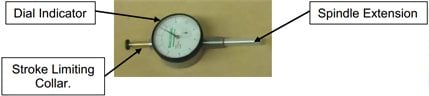 |
The Stroke of the Tube Sheet Pit Gauge is limited to approximately 0.100 (2.5mm) by the collar installed over the upper portion of the Dial Indicator's Spindle. This is done to ensure linearity between the Contact Point Spring and the internal Brass Plunger. As one reads on, the reason for the limited stroke is covered below. If a slightly longer stroke is required, the Limiting Collar can be shortened, thus increasing the Pit Gauge Stroke.
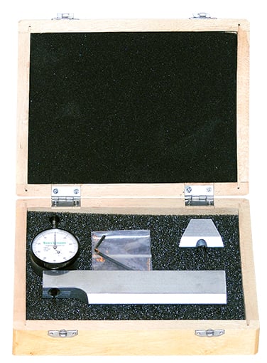
Top End Assembly Top End Assembly
The Top End Assembly is made completely of custom made parts. The following is a description of them and a guide to there function; | 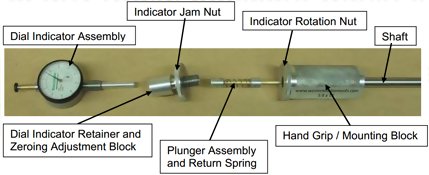 |
Dial Indicator Assembly
Provides the operator with a direct measurement of Pit Depth. Ancillary parts toWestern's Push To Read Indicators are; Plunger Stroke Limiting Collar, and theSpindle Extension. The Spindle Extension should be regularly checked to ensureit is tight.
Dial Indicator Retainer and Zeroing Adjustment Block
The Retainer is fitted with an #8-32 Set Screw to Lock the Dial Indicator to theRetainer. Further, the position of the Dial Indicator can be slightly adjusted withinthe Retainer.
The Retainer is rotated in and out of the Hand Grip / Mounting Block to GaugeZero the Dial Indicator. However, general Zeroing will be done with both Gauge Zeroing and Dial Zeroing.
Indicator Jam Nut
The Jam Nut locks the Retainer to the Indicator Rotation Nut, to keep the Zero ofthe Gauge when the Hand Grip (and Shaft) are rotated. If the Indicator Jam Nut is not tight up against the Rotation Nut, and the Hand Grip is rotated, the Zero will be lost.
Plunger Assembly
The Plunger Assembly simply connects the Dial Indicator to the Contact Point Spring. This assembly is easily removable on Standard Tube Sheet Pit Gauges, however on specials with a working length over 500 mm, it is not removable. The Plunger on specials is fitted with plastic centralizers to prevent sagging of the Plunger over there longer lengths. The Plunger on 1.5 meter Tube Sheet Pit Gauges is fitted with 4 Centralizers. The centralizers can not pass through the Hand Grip / Mounting Block, which is a press fit onto the tube with Anerobic Sealant to keep it together
The Return Spring helps the Dial Indicator's Plunger return to its home position (retracted). Normally, Western Instruments Dial Indicators are fitted with helper springs on the Top end of the Spindle, but the Stroke Limiter requires it to be located elsewhere |  |
Indicator Rotation Nut
With the Dial Indicator Zeroed (with and within the Retainer and the Hand Grip /Mounting Block), the operator is able to rotated the entire Pit Gauge assemblyand keep the face of the Dial Indicator in plain view.
The Indicator Rotation Nut is secured to the Hand Grip / Mounting Block by asecond #8-32 set screw. Unless damaged, there is no need to remove the HandGrip / Mounting Block from the Indicator Rotation Nut.
Hand Grip / Mounting Block
Obviously the operator manipulates the Pit Gauge by the Hand Grip. When the Pit Gauge is in the desired position, the operator secures the Contact Surface by wedging his finger between the Pit Gauge's Shaft and the ID of the Tube Sheet, with a slight amount of pressure up on the Hand Grip.
When the Contact Surface is moved to a new measurement location, the operator holds the Indicator Rotation Nut, to keep the Dial Indicator in his direct view. The knows the radial position of the Contact Surface (and Point) as the Hand Grip has a Reference Surface (or Flat) machined into it. The Reference Surface is directly opposite (180) from the Contact Surface at the Bottom End of the Tube Sheet Pit Gauges.
Bottom End Assembly
Again, the Bottom End Assembly is made completely of custom made parts. The following is a guide to there function; | |
Shaft
The main component of the Shaft is 3/8 inch (9.5mm) Diameter 300 Series Stainless Tube. Pressed into each end of this tube are the; Hand Grip / Mounting Block, and the Contact Surface Housing. Do not attempt to remove either of these press fit components, as damage will occur to every part rendering them useless.
Contact Surface Housing
Other than the Dial Indicator, this is the most delicate component of the Tube Sheet Pit Gauge. The Contact Surface Housing is precision machined, and includes a slot which guides the Contact Point through the Housing. Furthermore, this is the area where the Plunger Assembly pushes the Contact Point out andinto the target area.
Contact Point
The Contact Point is made from Spring Steel, and is given a travel distance ofapproximately 0.100 (2.5mm). As the Plunger Assembly impinges on the portion of the Contact Point that is at a 45 angle to the center line of the Shaft, the stroke of the Dial Indicator is limited by the Limiting Collar. This ensures that the Plunger is not allowed to travel to an area where the linearity of the Pit Gauge would be compromised. Considering the primary application of boiler tubing, the limited stroke is more than appropriate. If a slightly longer stroke is required, the Limiting Collar can be shortened, thus increasing the Pit Gauge Stroke.
Retainer Tube
The Retainer Tube secures the Contact point to its nesting area within the Contact Surface Housing.
Nose Cap
The Nose Cap keeps the Contact Point at a correct longitudinal position within the Contact Surface Housing and holds the Retainer Tube onto the Contact Surface Housing. When the Nose Cap is tightened by hand, it pushes the Contact Point even with the end of the Contact Surface Housing, which is the Contact Point's home position.
Operation
The operator should be completely comfortable with assembling and disassembling the Tube Sheet Pit Gauge, as its service conditions will require very regular adjustment and cleaning.
Gauge Zeroing
Gauge Zeroing is the adjustment of the Dial Indicator within the overall apparatus so the Indicator Needle reads zero and is at top dead center of the DialIndicator. We encourage Gauge Zeroing as the operator doesn't have to secondguess the readings he is getting from the Pit Gauge. An operator can neverGauge Zero often enough. A Zeroed Gauge is an accurate Gauge.
The Tube Sheet Pit Gauge is supplied with a Brass Zeroing Tube that is the same inside diameter as the outside diameter of the Pit Gauges Shaft andContact Surface Housing. The Zeroing Tube is simply slipped onto the ContactSurface Housing, directly over the Contact Point exit area. The Dial Indicator Retainer and Zeroing Adjustment Block is then moved in, to bring the Contact Point to a place where it is just touching the Zeroing Tube. One must be careful to feel the position where the two components (Contact Point and Zeroing Tube) engage one another. The Contact Point can not be so tight, that it locks the Zeroing Tube onto the Contact Surface Housing.
Dial Zeroing is often used to know the position of contact between the Contact Point and Zeroing Tube, and is often a nice way to adjust out the last 2 or 3 thousands of an inch (or hundredths of a millimeter) of movement to have the Dial Indictor Pointer to the 0 position. The operator must fully understand the importance of Zeroing, and should demonstrate it to his supervisor or customer.
Contact Point Replacement
Prior to replacing the contact point, the operator must loosen the Dial Indicator by backing off on the Dial Indicator Retainer and Zeroing Adjustment Block. If this is not done prior to replacing the Contact Point, the Plunger will interfere with the insertion of the new Contact Point.
The Contact Point should be replaced when the point is damaged or excessively worn. However, operators are encourage to dress the Contact Point before it is changed. Further, Contact Points can be sharpened by either grinding or filing. If the Contact Point becomes shorter due to dressing (sharpening), the Gauge is easily zeroed to compensate. Conversely, it is easiest to use the Tube Sheet Pit Gauge with a new, sharp Contact Point.
Insert the Contact point into the Slot on the Contact Surface Housing. Bring the Contact Point to the extreme Bottom End of the Contact Surface Housing, but leave a short length protruding past the end (as illustrated to the left). The Retainer Tube is then slipped over the Contact Surface Housing.
As the Nose Cap is tightened onto the Contact Surface Housing, it will push the Contact Point to its home position. The home position is even with the Bottom End of the Contact Surface
Housing. The operator can not rely on the Plunger to push the Contact Point home.
| After the Contact Point is replaced, the operator must re-zero the Pit Gauge. The operator should take the opportunity, when replacing the Contact Point, to clean the Contact Surface Housing, Plunger Tube, Nose Cap, etc. | 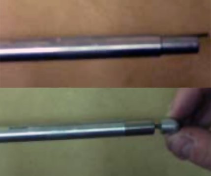 |
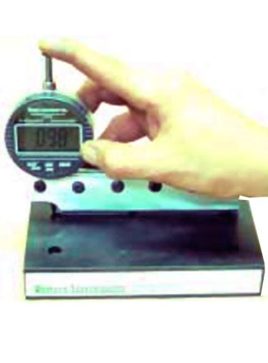
Taking Measurements
The Contact surface, from where the Contact Point extends, is simply aligned by the operator, against the target point. The reference surface or flat portion on the Hand Grip / Mounting Block is lined up with side where the Contact Point exits the Contact Surface Housing.
When the Contact Surface Housing of the Pit Gauge is in the desired radial position, of the Tube to be tested, the operator should rotated the Dial Indicator face into his field of view. The Contact Surface Housing must be secured against the ID Surface of the tube, this is typically accomplished by wedging a finger between the Pit Gauge Shaft and the ID of the Tube Sheet. The ContactSurface Housing is held fast to the target area with a slight amount of pressure, in the opposite direction of the target area, on the Hand Grip.
When larger Diameter Tubes are being tested, or on specials with a working length over 500 mm, this wedging technique isn't practical. The Operator then needs to be creative in finding ways to hold the Contact Surface Housing fast to the target area. This needs to be accomplished in such a fashion that doesn't damage the various components of the Tube Sheet Pit Gauge. Furthermore, if the Contact Surface Housing is not over a corrosion pit, this auxiliary holding must be firm enough not to allow the Contact Point to lift the Contact Surface Housing off the work piece. The operator must be mindful of this, and not push down on the Dial Indictor spindle with to much force.
To find Pitting, the operator can put a small amount of pressure on the Dial Indicator plunger, slightly extending the Contact Point out of the protection of the Contact Surface Housing. The operator then moves the Pit Gauge forward and back (and radially) over the ID Surface of the Tube being tested. This technique is similar to Scanning outlined in our other Pit Gauge Literature.
Maintenance
The Tube Sheet Pit Gauge is a precision engineered and manufactured instrument and must be treated as such. While the environment on Tube Bundles and Sheets of Heat Exchangers tends to be harsh, Tubes need to be cleaned. This cleaning should be in a similar fashion required by other NDE Techniques (UT, ET, or Remote Field).
While testing, the operator must be mindful of the build up of foreign material on and in the Tube Sheet Pit Gauge. Operators must not be tardy in their cleaning of the Pit Gauge. When cleaning, a mild soap solution with hot water is recommended, which requires a basin to soak parts in. After the disassembled unit is placed into the basin to soak, with the exception of the Dial Indicator, individual parts can be cleaned with a soft bristle bush. An old child's tooth brush works excellent for this purpose. Do not use abrasive cleaners or abrasive Scrubs on the Tube Sheet Pit Gauge. Extra long shaft assemblies will require sloshing of the soap solution within the Tube, with the plunger assembly inside.
If sharp scratches, slivers, or burrs form on the various parts of the Pit Gauge, they should be carefully removed with a fine jeweler's file. Removing to much material could interfere with the operation of the Tube Sheet Pit Gauge.
Warranty
Western Instruments warrants its products, against defects in materials and workmanship for a period of 1 year from receipt by the end user. If Western Instruments receives notice of such defects during the warranty period, Western Instruments will either, at its option, repair, replace, or condemn products that prove to be defective. Consumable items, such as Contact Points are warranted for 30 days, from receipt by the end user.
Any warranty is void if the unit has been modified in any way, or if it has been repaired by an unauthorized agency. The end user agrees that any equipment is disposition, when returned for warranty work, is at the full discretion of Western Instruments as to whether a claim is under warranty, or due to misuse. Western Instruments warranty shall overlook normal wear, however does not include operation outside the environmental specification of the product. All warranty work is FOB Western Instruments, and any returned units shall include a written description, by the end user, of the fault.
Western Instruments makes no other warranty, either expressed or implied, with respect to this product. Western Instruments specifically disclaims any liability arising form the use of this equipment. For the correct use of the product, refer to the Operating Instructions, furthermore we recommend instructional training to NACE, or other regulatory authority qualifications. Western Instruments highly recommends the end user exercise all possible safety precautions, including use of protective equipment, while operating this or other industrial equipment.
Downloads
| N88-TS Tube Sheet Pit Gauge Instruction Manual |